Extended Quantum Computing Patterns

Hadamard Test
Aliases: –
Tags:
© This pattern is originally published in L. Stiliadou, J. Barzen, M. Beisel, F. Leymann, and B. Weder, "Fundamental Patterns for Quantum Algorithms", in Proceedings of the 1st International Conference on Quantum Software (IQSOFT), Xpert Publishing Services (XPS), 2025.
Intent
How to calculate the expectation value of a unitary operator for a given quantum state?
Context
Given a unitary operator \(U\) acting on \(n\) qubits, and let \(\ket{\psi}\) be a \(n\)-qubit quantum state. Then, the expectation value \(\bra{\psi}U\ket{\psi}\) should be estimated.
Forces
Determining the expectation value classically is computationally expensive and scales exponentially with the number of qubits [Bravyi and Gosset, 2016]. Quantum devices enable solving this problem more efficiently [Aharonov et al, 2006]. However, using today's quantum devices also leads to additional challenges. For example, large quantum circuits can not be executed successfully, and results are prone to errors [Preskill, 2018].
Solution
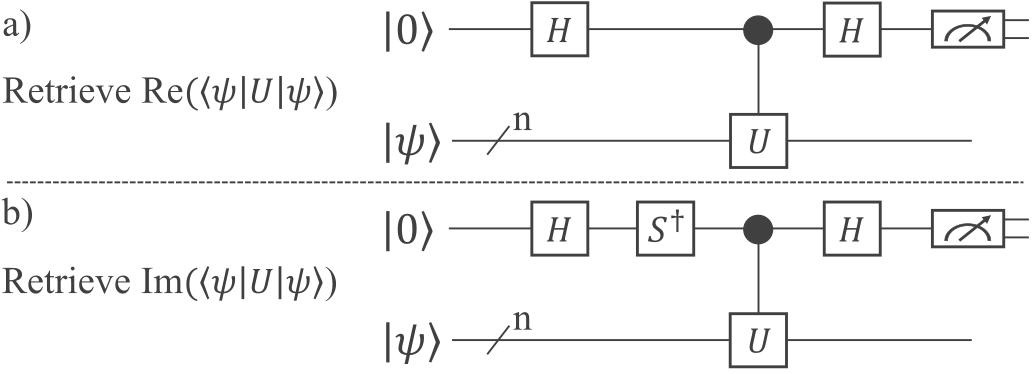
The sketch gives an overview of the structure of the quantum circuit, which is required to perform a Hadamard test. The quantum circuit requires one ancilla qubit on which a Hadamard gate is applied to bring it into an equal superposition. Subsequently, depending on whether the real (see a) or imaginary part (see b) of \(\bra{\psi}U\ket{\psi}\) should be retrieved, a \(S^\dag\) gate is added. Next, the unitary operator \(U\) is applied in a controlled manner by using the ancilla qubit as the control qubit. Due to a so-called phase-kickback, the information is transferred from the target register to the control qubit when entangling the qubits with the controlled \(U\) gate [Ossorio-Castillo et al., 2023]. Finally, another Hadamard gate is applied to the ancilla qubit enabling the retrieval of the expectation value \(\bra{\psi}U\ket{\psi}\) by measuring the ancilla qubit.
Result
The real or imaginary part of the expectation value \(\bra{\psi}U\ket{\psi}\) is the output after measuring the ancilla qubit. Depending on the required upper bound of the absolute error, the number of samples must be increased.
Examples
–
Related Patterns
The HADAMARD TEST can be implemented using the QUANTUM MODULE pattern [Bühler et al., 2023], i.e., separating the inputs from the code generation logic required to create the quantum circuit realizing the Hadamard test. To implement the SWAP TEST pattern, the input quantum state \(\ket{\psi}\) can be separated into two states to be compared, and the SWAP gate is applied as the unitary operator \(U\).
Known Uses
The Hadamard test is utilized within the Aharonov–Jones–Landau algorithm to compute the Jones polynomial [Aharonov et al., 2006]. Furthermore, the Hadamard test can also be used for variational quantum algorithms to determine the gradient of the objective function [Harrow and Napp, 2021]. [Arad and Landau, 2010] utilize the Hadamard test in the context of tensor networks. [Xu et al., 2022] employ the Hadamard test as the measuring method for a variational quantum support vector machine.